Successful sealing involves containment of fluid within fluid power systems and components while excluding contaminants.
What is in this article?:
- Seals and sealing technology
Successful sealing involves containment of fluid within fluid power systems and components while excluding contaminants.
High-pressure sealing generally refers to confining fluids at pressures above 5,000 psi. Below these pressures, standard energized urethane lip seals and U-cup seals function satisfactorily without special provisions. Above them, some sort of special sealing devices are necessary.
To be effective, seals have to perform three basic functions. They must:
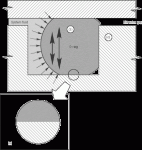 |
| Fig. 1 (a) Seal material must conform to irregularities in metal surfaces to block fluid passage; (b) to adjust to clearance gap size changes, the seal must expand or compress rapidly to follow dimensional variations; (c) to resist being forced into the extrusion gap, the seal must have sufficient modulus and hardness to withstand shear stress produced by system pressure.
|
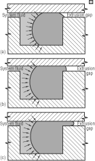 |
| Fig. 2. As system fluid pressure increases, (a) to (b), an O-ring seal is progressively forced into the extrusion gap. Finally, (c), the physical limits of the seal material have been exceeded.
|
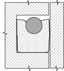 |
| Fig. 3. Standard PolyPak in modified urethane such as Molythane can be used at pressures to 5,000 psi. Higher modulus elastalloys such as PolyMyte, in the basic PolyPak configuration, operate successfully to 7,000 psi at moderate temperatures and standard tolerances.
|
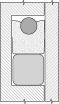 |
| Fig. 4., left, A standard PolyPak with a modular backup ring of elastalloy such as PolyMyte will seal successfully to 12,000 psi.
|
| Fig. 5. A positively activated PolyPak of modified urethane such as Molythane with a backup ring of Nylatron can seal to 10,000 psi.
|
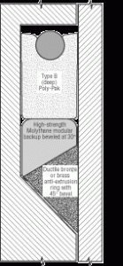 |
| Fig. 6. At extreme pressures, a metal anti-extrusion device of ductile bronze or brass and a high-strength, high-durometer modular backup ring is required.
|
Seal — Sealing elements must conform closely enough to the microscopic irregularities of the mating surfaces (rod to seal groove and/or piston groove to cylinder bore, for example) to prevent pressure fluid penetration or passage, Figure 1.
Adjust to clearance-gap changes — The seal must have sufficient resilience to adjust to changes in the distance between mating surfaces during a cylinder stroke. This clearance gap changes size because of variations in the roundness and diameter of the cylinder parts. The clearance gap also may change size in response to side loads. As the size of the gap changes, the seal must match the size change to maintain compressive sealing force against adjacent mating surfaces.
Resist extrusion — The seal must resist shear forces that result from the pressure differential between the pressurized and unpressurized sides of the seal. These shear forces attempt to push the elastomeric seal into the clearance gap between adjacent metal surfaces, Figure 2. The seal must have sufficient strength and stiffness to resist becoming deformed into the gap and damaged or destroyed.
Higher pressure improves sealing
Elastomeric materials also must seal while accommodating dimensional variations caused by manufacturing tolerances, side loads, and cylinder deformations under pressure. Understand that in general, sealing improves as fluid pressures increase. System pressure on the seal surface attempts to compress the seal axially. This compression forces the seal more tightly into the gland and helps improve conformability of the seal with its contacting metal surfaces.
If the clearance gap increases during the stroke, resilience of the compressed elastomeric seal causes it to expand radially and maintain sealing force against the metal surfaces. System pressure combines with seal resilience to increase compressive sealing forces when the clearance gap increases. It generally is true that, as system pressure increases, sealing force and the resulting sealing effectiveness also increase if the seal is correctly designed.
The seal’s internal shear stresses increase as system pressure increases. With increasing pressure, the stresses eventually exceed the physical limits of the seal elastomer, and it extrudes into the gap. Difficulties presented by high pressure are not primarily sealing problems but are problems of keeping the seal in its gland while maintaining its structural integrity as increasing system pressures force the seal into the gap.
Almost all of the design and in-service technology of high-pressure sealing deals with protecting the elastomeric seal from the potentially destructive distortion caused by high system pressures. With proper backup to reduce the size of the gap, relatively fragile elastomers can successfully seal extremely high pressures.
When handling a 90-durometer energized urethane lip seal or U-cup at room temperature, the seal seems to be made of an extraordinarily stiff, tenacious material. It requires well-designed experiments and/or sophisticated computer simulations to visualize the state of such a seal inside a hydraulic cylinder at normal operating temperatures and pressures. At pressures as low as 600 psi for 70-durometer nitrile rubber and 1,500 psi for 90-durometer urethane, the seal cross section is significantly deformed. It changes shape almost instantaneously in response to pressure spikes or changes in the size of the clearance gap. Literally, the seal becomes an annular glob in the seal gland.
Advertisement:
Seal extrusion
The ability of a seal to resist extrusion into the gap depends on the interaction of:
- system operating pressure,
- system operating temperature,
- size and type of clearance gap,
- seal material, and
- seal design.
System operating temperature is especially important in high-pressure applications because most elastomers soften and lose their ability to resist extrusion at higher temperatures. Some design methods that help lower high system temperatures include the use of low-friction materials, an increase in fluid volume, and a decrease in the cycle rate of the system. However, when ambient temperature is high, and operating conditions are extreme, it is possible for system temperatures to exceed design parameters. Under such conditions, it often becomes necessary to upgrade seals, and for anti-extrusion devices to be more temperature-resistant.
The size of the extrusion gap can be controlled throughout the design and manufacture of the cylinder, piston, rod, and end cap. Decreasing manufacturing tolerances increases cylinder cost, however, and also may increase the probability of metal-to-metal interference. In addition, reducing the extrusion gap size is inherently limited by differential thermal expansion of mating metal components.
The actual size of the extrusion gap is a function of:
- the nominal gap designed into the cylinder,
- manufacturing tolerances, including diametrical variation and ovality,
- diametrical expansion of the cylinder caused by system pressure,
- side loads, and
- wear on radial load-bearing surfaces.
Because all these factors vary, and because the variances can be cumulative, seal design and material must resist extrusion through the largest gap likely to be encountered at design pressure and temperature.
The right material is essential
The key to high-pressure sealing is the use of a material or a combination of materials that has sufficient tear strength, hardness, and modulus to prevent extrusion through the gap. At pressures of 5000 to 7000 psi, the strongest elastomeric materials in standard seal configurations resist the extrusion without reinforcement. At higher pressures, the elastomeric sealing element must be backed by a higher modulus and harder material. Various more-or-less standard backup configurations have demonstrated their effectiveness over many years.
At pressures in excess of 20,000 psi, the extrusion gap must be closed and the elastomeric seal must be protected by a sequence of progressively harder, higher-modulus materials. Properly designed, this progression of materials prevents extrusion, tearing, cutting, or other destructive deformation of the elastomeric seal and distributes loads more uniformly to the element that bridges the gap.
Designs and materials
In high-pressure applications, material characteristics, such as high modulus, tear strength, self-lubrication, and abrasion resistance, become increasingly important. The following seal configurations and materials are specially suited to high-pressure applications. Although these examples cite proprietary compounds as typical, other manufacturers offer their own proprietary compounds, which generally have similar properties.
Abrasion-resistant and self-lubricating materials should be used at high pressures because friction increases there. Some of these materials are:
Enhanced polyurethane — At the lower end (5,000 psi) of the high-pressure continuum, a standard PolyPak configuration of modified polyure-thane energized by a resilient O-ring elastomer, Figure 3, is sufficient. Polyurethane-based materials — such as Molythane (impregnated with molybdenum disulfide to provide dry lubrication plus good compatibility with lubricating properties of working fluids) – are suitable for application pressures up to 5,000 psi without backups. Molythane comes in a 90-Shore A durometer formulation for PolyPak seals and in a 65-Shore D durometer formulation with a higher modulus for increased extrusion resistance for anti-extrusion devices. Ultrathane K-24, a high-tensile, reduced-friction, enhanced-urethane material also is suitable for applications to 5,000 psi without reinforcement.
Elastalloy co-polymers — Various elastoplastic or elastalloy copolymers, such as PolyMyte — a material with high tear strength, abrasion resistance, hardness (Shore D 65), and modulus — offer high pressure performance capabilities. PolyMyte configured as PolyPak and energized by a resilient elastomeric O-ring is suitable for applications up to 7000 psi without backups. A high-durometer PolyMyte modular backup, Figure 4, used in conduction with a Molythane PolyPak, can withstand pressures up to 12,000 psi or more.
Non-elastomeric materials. Non-elastomers include polyamide resins such as nylons and modified nylons and metal backup rings, typically ductile bronze or brass.
One non-elastomer is Nylatron, a glass-filled polyamide resin. A Molythane PolyPak with a positively actuated Nylatron backup ring inserted to bridge the extrusion gap, Figure 5, can be used successful at pressures to 10,000 psi.
For extreme pressures in one direction, a three-part sealing system, Figure 6, is recommended. The seal is made of a Type B PolyPak, backed by a filled-polyamide modular backup beveled at 30°. A wedge-shaped, skive-cut split-ring, machined from ductile bronze or brass, is placed behind the beveled modular backup. The metal backup and seal groove are mated at a 45° angle. Under pressure, the wedge-shaped metal ring expands to close the extrusion gap. This design has operated successfully at pressures to 100,000 psi in a specialized application for making synthetic diamonds.
Compressed by the elastomeric urethane PolyPak, this elastoplastic modular backup expands radially to fill the groove and prevent sealing-element extrusion. Without an additional anti-extrusion device, the elastoplastic modular backup would experience plastic flow into the gap at 100,000 psi. A softer, lower tear-strength urethane back-up element would be nibbled or cut by the metal backup ring especially where the metal ring is split.
These proven designs and materials are typical of those available to increase the pressure capabilities of elastomeric seals in dynamic applications.
Many other materials can be suitable for high-pressure applications. Often, the choice of seal materials is dictated by the fluid medium, system operating temperatures, cost, or system pressure. The potentially higher efficiency of high-pressure systems comes at a slight cost premium. Sealing materials for high pressures are more expensive, and seal designs often are more complicated. Higher sealing pressures increase sealing force and friction. Increased friction causes higher wear rates and may require more frequent seal replacement, but frictional force and wear rates typically increase more slowly than pressure.
Hydraulic system design today often seems to focus on dramatic high-pressure applications. For example, the aerospace industry is presently evaluating 8,000-psi systems for future aircraft in special test beds, such as Lockheed-Georgia’s HTTB. Many successful high-pressure systems incorporate innovative seal designs in both static and dynamic modes of operation.
| Table 1: Average dynamic and static squeeze levels – in. | ||||||
| Seal cross-section | Gland packing space | Squeeze or compression | Percent compression | |||
|---|---|---|---|---|---|---|
| Dynamic | Static | Dynamic | Static | Dynamic | Static | |
| 0.070 | 0.0565 | 0.0510 | 0.0135 | 0.0190 | 19.3 | 27.1 |
| 0.103 | 0.0900 | 0.0820 | 0.0130 | 0.0210 | 12.6 | 27.1 |
| 0.139 | 0.1225 | 0.1120 | 0.0165 | 0.0270 | 11.9 | 19.4 |
| 0.210 | 0.1870 | 0.1715 | 0.0230 | 0.0385 | 11.0 | 18.3 |
| 0.275 | 0.2400 | 0.2275 | 0.0350 | 0.0475 | 12.7 | 17.3 |
Urethane and vegetable oilsThe properties of urethane have made it a popular material for a broad range of hydraulic-sealing applications. However, one negative factor is its susceptibility to hydrolysis. As urethanes are produced, water is the byproduct of the chemical reaction. If water is re-introduced to urethanes later at a temperature high enough (generally 140° F) to cause a second chemical reaction, polymer bonds are broken and the urethane begins to deteriorate. The material hardens and then flakes apart. This phenomenon is known as hydrolysis. If a urethane seal is exposed to ambient water – and particularly hot water or steam – for extended periods, the seal may disintegrate completely. Many vegetable oils have an inherent property of water absorption. If such oils are installed in hydraulic systems, their water component introduces a fluid mixture which jeopardizes seal performance. This phenomenon prohibits the use of conventional urethane seals with vegetable oils (as well as water-based or water-mixed fluids) in common hydraulic applications – which typically run at temperatures high enough to precipitate hydrolysis. |
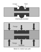 |
| Fig. 7. Simple representation of how squeeze force compresses a combination gasket/O-ring seal during gland assembly.
|
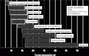 |
| Fig. 8. Percentage compression set exhibited by typical families of sealing elastomers used in fluid power systems.
|
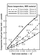 |
| Fig. 9. Plots of compressive load vs. O-ring seal cross-section for three different seal material hardnesses.
|
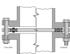 |
| Fig. 10. Cross-sectional sketch of a combination gasket/ O-ring seal before and after installation.
|
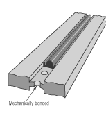 |
| Fig. 11. The basic element of a combination gasket/O-ring seal is a retainer with grooves in one or both surfaces into which an elastomer is molded.
|
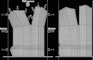 |
| Fig. 12. The illustration to the left is an FEA mesh model of a U-cup cross section, while at right is the deformed shape after installation.
|
Low-pressure considerations
Almost every hydraulic system, however, will face occasions when the equipment is not operating, and the pressure falls to zero. Or, in some applications, the system’s pressure may never exceed 100 psi. These are typical of the types of operations defined as low pressure; that is, when the confined fluid media exert little or no pressure force on the sealing element to affect or augment a seal.
Within the framework of low-pressure sealing, several primary design considerations affect sealability:
- seal squeeze,
- compression set,
- sealing force,
- gland surface finish conditions, and
- molding flash.
Squeeze
A seal component is generally installed in a groove machined into one of the surfaces to be sealed. As the two surfaces are brought together to form a gland, they squeeze the diametral cross section of the seal. The mechanical squeezing action deforms the seal cross section; the degree of deformation obviously is a function of the squeezing force. In low-pressure applications, the tendency of the squeezed elastomer to maintain its original shape creates a seal. As the elastomer shape is deformed in its gland, it exerts a counter force against the mating surfaces equal to the force squeezing it, Figure 7, and hence, provides the available sealing force.
Thus, squeeze is a major low-pressure consideration. The recommended squeeze levels are a function of seal cross section, the application conditions and whether the application is dynamic or static.Dynamic compression typically is lower than static compression, due to seal wear and friction considerations. Table 1 summarizes dynamic squeeze levels as defined by MIL-G-5514F – a document which is a good guide to those parameters. Static data in the table are summarized from common industrial practice.
Compression set
Compression set reflects the partial loss of memory due to the time effect. In hydraulic systems operating over extreme temperature ranges, it is not uncommon for compression-type seals, such as O-rings, to leak fluid at low pressure because they have deformed permanently or taken a set after used for a period of time. The term compression set refers to the permanent deflection remaining in the seal after complete release of a squeezing load while exposed to a particular temperature level. As related to low-pressure sealing, set-the loss of memory-reduces the compressive sealing force.
Compression set is expressed as a fraction of the initial squeeze. Thus, a 0% compression set value indicates complete recovery from a compressive load, producing the maximum possible compressive sealing force. A 100% set value indicates no recovery or rebound at all. A seal in this condition will no longer provide a sealing force and hence, has no ability to act as a low-pressure seal. The bar graph in Figure 8 depicts the range of typical compression set values for various sealing elastomers. Of course, compression set properties are a major but not the only factor affecting elastomer choice for low-pressure sealing. Compatibility with various hydraulic fluids must be considered as well.
Sealing force
There are several factors affecting the sealing force:
- material hardness,
- percentage squeeze, and
- seal cross-section size.
For a certain amount of squeeze, the sealing force is directly related to the hardness or elastic moduli of seal materials for low-pressure applications. The harder the material, the larger the initial sealing force. A seal material has a nonlinear stress-strain curve and needs to be described by special material models. For simplicity, linear moduli, such as Young’s modulus and shear modulus, are usually used due to their direct relations to the material hardness. The modulus commonly used for specification purpose is tensile stress at a specified elongation. For example, modulus at 100% elongation is the tensile stress corresponding to that elongation.
Hardness generally is measured with a durometer gage – typically using the Shore A scale. The gage measures the force required to deflect the flat surface of a rubber specimen with a pointed indicator. The A scale ranges from 0 to 100; a 90 Shore A compound would be designated as a hard (or high-viscosity) material, and would exhibit much higher compressive force than a 60 Shore A compound, which would be classified as soft.
For a specific material, seal compression force of the elastomeric material increases as the percentage deflection of the seal’s diametral cross- section increases. Dynamic squeeze levels typically should be limited to around 12% due to friction and related-wear considerations. Static squeeze levels can be as high as 30%.
It generally is recommended that a minimum of 0.009-in. squeeze be induced on radial seal cross sections due to compression set considerations. Maximum radial squeeze should be held to 30% because greater squeeze causes assembly difficulties and elastomer deterioration. Compressive sealing load is also directly related to the size of seal’s cross-section, Figure 9.
