Cylinders
What is in this article?:
- Cylinders
- Common variations
- Mounting
When hydraulic or pneumatic systems must produce linear motion, cylinders become their most important component by converting fluid pressure and flow to force and velocity respectively.

The linear motion and high force produced by cylinders are big reasons why designers specify hydraulic and pneumatic systems in the first place. One of the most basic of fluid power components, cylinders have evolved into an almost endless array of configurations, sizes, and special designs. This versatility not only makes more-innovative designs possible, but makes many applications a reality that would not be practical or possible without cylinders.
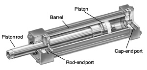 |
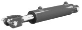
| Fig. 1. Cutaway view shows key features of a typical cylinder, in this case, a double-acting model for hydraulic service with standard tie-rod construction.
|
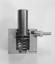 |
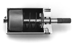
| Fig. 2. Cut-away view shows key features of a single-acting cylinder. This particular model is base-mounted with an extension spring for a tool holding application.
|
 |
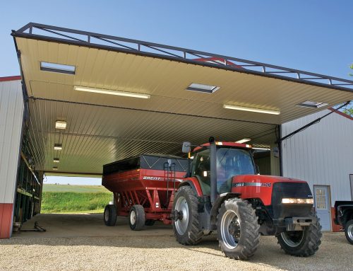
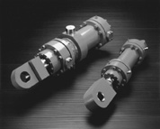
| Fig. 3. Welded cylinders combine benefits of heavy-duty construction with compact design, which is the main reason why they are widely used in mobile-equipment applications.
|
 |
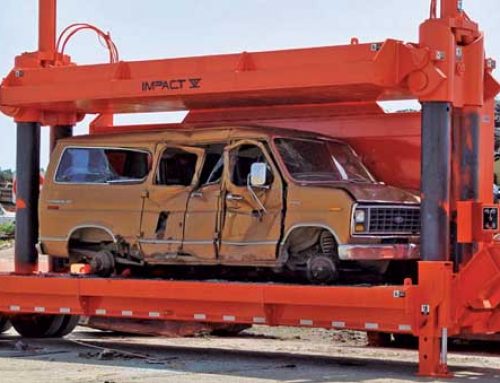
| Fig. 4. Mill-duty cylinders have flanges welded to both ends of their barrel with an end cap bolted to each flange.
|
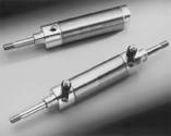 |
| Fig. 5. Non-repairable cylinders generally are constructed primarily of stainless steel, aluminum alloys, and engineered plastics for pneumatic or low-pressure hydraulic service. Shown here are a single-acting, spring-return model, top, and double-acting with double rod-end, bottom.
|
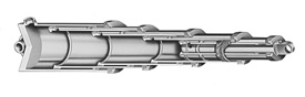 |
| Fig. 6. Telescoping cylinders have two or more stages that, when fully extended, can produce a stroke that exceeds the length of the cylinder when fully retracted. Shown here is a cutaway of a six-stage single-acting model.
|
| Fig. 7. Short-stroke cylinders have a piston diameter that exceeds rod length. They are used where axial space is limited and high force must be generated from a relatively low supply pressure.
|
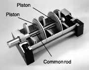 |
| Fig. 8. Tandem cylinders use multiple pistons connected through a common rod to generate relatively high force from a low supply pressure and small bore.
|
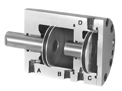 |
| Fig. 9. Duplex cylinders have multiple pistons that are not connected to a common rod. Actuating individual piston chambers achieves multiple strokes.
|
 |
| Fig. 10. By eliminating the conventional sliding piston seal – and its inherent tendency toward stick-slip operation – diaphragm cylinders produce nearly frictionless motion, except for the miniscule amount of friction at the rod seal. The diaphragm’s positive sealing also eliminates the potential for leakage around the piston.
|
Cylinder basics
The most common cylinder configuration is double acting, Figure 1. Routing pressurized fluid into the rod end of a double-acting cylinder causes the piston rod to retract. Conversely, routing pressurized fluid into the cap end causes the rod to extend. Simultaneously, fluid on the opposite side of the piston flows back into the hydraulic reservoir. (If air is the fluid medium, it usually is vented to the atmosphere.)
Because the area of the rod-end piston face is smaller than the cap-end area, extension force is greater than retraction force (assuming equal fluid pressures). Because total cylinder volume is less with the cylinder fully retracted (because of rod volume) than when the cylinder is fully extended, a cylinder retracts faster than it extends (assuming equal flow rates).
Single-acting cylinders, Figure 2, accept pressurized fluid on only one side of the piston; volume on the other side of the piston is vented to atmosphere or returns to tank. Depending on whether it is routed to the cap end or rod end, the pressurized fluid may extend or retract the cylinder, respectively. In either case, force generated by gravity or a spring returns the piston rod to its original state. A hydraulic jack for vehicles represents a common application of a single-acting, gravity-return cylinder.
Single-acting cylinders can be spring-extend or the more common spring-return type. A spring-extend cylinder is useful for tool-holding fixtures because spring force can hold a workpiece indefinitely. The cylinder then releases the workpiece upon application of hydraulic pressure. Spring-applied/hydraulic-pressure-released (parking) brakes represent another common application of single-acting, spring-extend cylinders.
But the most common type of single-acting cylinder uses a return spring. In this version, pressurized fluid enters the cap end of the cylinder to extend the piston rod. When fluid is allowed to flow out of the cap end, the return spring exerts force on the piston rod to retract it. Factory automation – especially material handling – is a common application using pneumatic spring-return cylinders
Standard constructions
Construction variations for single-and double-acting cylinders are based primarily on how the two end caps are attached to the barrel. Additional variations include wall thickness of the barrel and end caps, and materials of construction.
Tie-rod cylinders, Figure 1, have square or rectangular end caps secured to each end of the barrel by rods that pass through holes in the corners of the end caps. Nuts threaded onto the end of each tie rod secure the end caps to the barrel. Static seals in the barrel/end-cap interface prevent leakage. A number of variations to this design exist, including use of more than four tie rods on a cylinder, or long bolts that thread into tapped holes in one of the end caps.
The majority of cylinders for industrial, heavy-duty applications use tie-rod construction and usually conform to National Fluid Power Association (NFPA) standards. These standards establish dimensional uniformity so cylinders from multiple manufacturers can be interchanged. However, care should be taken when interchanging cylinders because even though it conforms to NFPA dimensional standards, a cylinder may have proprietary features from its specific manufacturer that may not be available from a different manufacturer.
Welded cylinders, Figure 3, have end flanges welded to the barrel and an end cap attached to each flange. End caps are secured in place by bolts that slip through holes in each end cap and thread into tapped holes in each end flange. This construction is lighter and more compact than the standard tie-rod configuration, which explains why welded cylinders find wide application in mobile equipment.
A variation to this construction has each end cap threaded into the end of the barrel. This construction, however, usually cannot accommodate as high a pressure rating as welded and can be more difficult to disassemble and reassemble.
Mill-duty cylinders, Figure 4, have flanges welded to the ends of the cylinder barrels with end caps of the same diameter as the flanges. Bolts secure the end caps to the flanges. Their construction is similar to that of welded cylinders, but mill-duty cylinders have thicker barrel walls and heavier construction in general.
Large mill-duty cylinders often have a barrel wall thick enough for the end-cap bolts to be threaded directly into the barrel wall. As the name implies, these cylinders were originally designed for use in steel mills, foundries, and other severe-duty applications.
At the other end of the duty spectrum are non-repairable cylinders, Figure 5. These cylinders are designed for economy and have end caps welded to the barrel to make them throwaway components. They cannot be disassembled for repair or seal replacement. However, this design proves very cost effective when high service life is not required. Most of these cylinders have stainless steel end caps and barrel, but because they are intended primarily for light duty cycles, many make extensive use of aluminum alloys and plastics for light weight and economy.
An alternative method of manufacture rolls the tube into a slot on the end caps to mechanically lock the three pieces together. Another alternative design has the end cap welded to the barrel and a rod-end cap secured via threads or a lock ring. These modifications allow disassembling the cylinder for repair but also raise its initial cost.
Cylinders
What is in this article?:
- Cylinders
- Common variations
- Mounting
When hydraulic or pneumatic systems must produce linear motion, cylinders become their most important component by converting fluid pressure and flow to force and velocity respectively.
More Than Seal & Cylinders………Solutions!
More Than Seal & Cylinders………Solutions!
<
Commmon variations
The most common type cylinder is the single-rod end, in which the rod is nearly as long as the cylinder barrel. The rod protrudes from the rod-end cap to transmit the generated force to the load. A double rod-end cylinder, Figure 5, has a rod attached to both faces of the piston with each rod extending through a rod end cap. Double rod-end cylinders are useful for moving two loads simultaneously, and they also eliminate the differential area between the rod side and blank side of the piston. With equal areas (and cylinder volumes) on both sides of the piston, a given flow produces the same extension and retraction speeds.
Most telescoping cylinders, Figure 6, are single acting, although double-acting versions are available. Telescoping cylinders contain five or more sets of tubing, or stages, that nest inside one another. Each stage is equipped with seals and bearing surfaces to act as both a cylinder barrel and piston rod. Available for extensions exceeding 15 ft, most are used on mobile applications where available mounting space is limited. The collapsed length of a telescoping cylinder can be as little as 15 its extended length, but the cost is several times that of a standard cylinder that can produce equivalent force. Models are available in which all stages extend simultaneously or where the largest stage extends first, followed by each successively smaller stage.
Ram cylinders are a special type of single-acting cylinders that have a rod OD the same diameter as the piston. Used mostly for jacking purposes, ram cylinders must be single acting because there is no internal cylinder volume to pressurize for retracting the rod. Ram cylinders sometimes are called plunger cylinders and are most often used for short-stroke applications. Most do not use return srpings, but, rahter, gravity or the load to retract the piston rod.
Short-stroke cylinders, Figure 7, generally have a rod length that is less than the piston diameter. It is used where high force must be generated from a relatively low supply pressure. Short-stroke cylinders also fit into a narrow axial space but require substantial radial width. These cylinders lend themselves to air-operated, automation machinery.
Tandem cylinders, on the other hand, are designed for applications where high force must be generated within a narrow radial space where substantial axial length is available. A tandem cylinder, Figure 8, functions as two single rod-end cylinders connected in line with each piston inter-connected to a common rod as well as a second rod which extends through the rod-end cap. Each piston chamber is double acting to produce much higher forces without an increase in fluid pressure or bore diameter.
Duplex cylinders also have two or more cylinders connected in line, but the pistons of a duplex cylinder, Figure 9, are not physically connected; the rod of one cylinder protrudes into the non-rod end of the second, and so forth. A duplex cylinder may consist of more than two in-line cylinders and the stroke lengths of the individual cylinders may vary. This makes them useful for achieving a number of different fixed stroke lengths, depending on which individual pistons are actuated.
Diaphragm cylinders, Figure 10, are either of the rolling diaphragm or the short-stroke type. Both use elastomeric diaphragms to seal the barrel-piston interface. The short-stroke type uses an elastomer sheet secured between halves of the cylinder body and is commonly used for truck and bus air-brake applications. The rolling diaphragm cylinder has a hat-shaped diaphragm that rolls into the cylinder barrel as the piston advances. Both types require very low breakout forces, have zero leakage, and are single-acting, spring returned.
General system design
Cylinders – and all components for that matter – should be readily accessible to ease installation and subsequent maintenance. If a fitting cannot be checked for tightness without first removing adjacent lines, for example, there is little incentive to bother fixing minor leaks that may occur.
Consider all components and fluid conductors of the system to
be elastic: they will flex and change length due to changes in fluid pressure, temperature, and strain. These changes are not minor. A pressure pulse to 6,000 psi will elongate a steel cylinder with a 24-in stroke by 0.024 in. If made of aluminum or cast iron, the cylinder can elongate about 2 to 2.5 times as much. If this elongation has not been accounted for in the design of the machine, the system eventually will leak, even if the latest fitting technology has been used. If previous installations have continually leaked, take this as clear evidence that a new design approach would be beneficial.
Cylinder life
An industrial cylinder should have a design factor of about 4:1 based on yield at rated system pressure. Many manufacturers of heavy-duty cylinders for mobile equipment specify a 3:1 design factor. A 15,000-psi stress at rated system pressure, with smooth system operation and no pressure pulses, is considered conservative. System pressure spikes that cause 30,000-psi stress often are not alarming, but at 30,000-psi unit stress, steel’s dimensional change is 0.001 in./in. of length. For a 30-in. cylinder, a pressure spike of that intensity causes a length change of almost 1/32 in. Dimensional changes in stressed cylinders, or those subjected to wide temperature changes, may further limit allowable working pressures.
Large dimensional changes can seriously affect performance and life expectancy of nonmetallic cylinder seals. For example, extrusive failures of 80 Shore A durometer, synthetic Nitrile seals can occur when clearance exceeds 0.004 in. at fluid pressures over 3,000 psi, or a 0.001-in. clearance with system pressure of 6000 psi. Such pressures can easily be reached in systems using differential cylinders or those with meter-out flow controls.
You must consider system shock pressures. If the hydraulic system contains speed control or energy-absorbing devices, pressure spikes can occur that are two to three times above normal system pressure. Therefore, determine the loading the cylinder will experience and then mount accordingly to maintain port seal integrity.
- Prev
- 1
- 2
- 3
- 4
- Next
More Than Seals & Cylinders…………….Solutions!
Cylinders
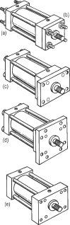 |
| Fig. 11. Fixed cylinder mounts that provide straight-line force transfer are: (a) tie rods extended, and extended both ends (a + b); (c) head rectangular flange, (d) head square flange; and (e) rectangular head which provides same service as (c) but uses entire head rather than an added flange. Cap flange mounts are the same as (c) and (d) but bolt to cap (not shown). Rectangular caps also are available.
|
| Fig. 12. As with other NFPA standardized mountings, centerline lug mounts provide striaght-line transfer of force.
|
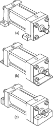 |
| Fig. 13. Side mounted cylinders include side lug (a), side end angle (b), side and lug (c), and side tapped (not shown). These mounts produce a turning moment as the cylinder applies force to the load.
|
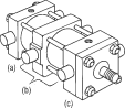 |
| Fig. 14. Pivot mounts absorb force along centerline and actuate loads that travel through arc. Cap trunnion (a), intermediate fixed trunnion (b) can locate anywhere between head and cap, and head trunnion (c) are versions of this style; only one of these versions is used at one time. The cylinders shown in Figures 3 and 6 employ clevis mounting, which is a type of pivot mounting for loads that travel through arc.
|
fluid pressure and flow to force and velocity respectively.
What is in this article?:
- Cylinders
- Common variations
- Mounting
When hydraulic or pneumatic systems must produce linear motion, cylinders become their most important component by converting fluid pressure and flow to force and velocity respectively.
More Than Seals & Cylinders…………….Solutions!
More Than Seal & Cylinders………Solutions!
Mounting
Trouble-free use of fluid power cylinders and their ability to serve and remain leak-free depends, in large part, on properly mounting the component for the particular application. The designer must determine the loading the cylinder will experience and mount it accordingly.
The National Fluid Power Association, NFPA, has standardized on a number of dimensions for square-headed tie rod cylinders to promote cylinder interchangeability between manufacturers. Part of this standardization program includes cylinder mounting styles, which generally provide:
- straight-line force transfer with fixed mounts that absorb force on the centerline of the cylinder
- straight-line force transfer with fixed mounts that do not absorb force on the centerline of the cylinder, and
- pivot force transfer with pivot mounts which absorb force on the centerline of the cylinder and allow the cylinder to change alignment in one plane.
Straight line – Cylinders with fixed mounts that absorb the force on the centerline of the cylinder are considered the best for straight line force transfer. Tie rods extended, flange, or centerline lug mounts are symmetrical and allow the thrust or tension forces of the piston rod to be distributed uniformly about the cylinder centerline, Figure 11. Mounting bolts are subjected to simple tension or shear without compound forces; when properly installed, cylinder bearing sideloading is minimized.
Cylinder tie rods are designed to withstand maximum rated internal pressure, and can be extended at either end and used to mount the cylinder. When the tie rods extend at both ends of the cylinder, one end can be used for cylinder mounting and the opposite end can support the cylinder or be attached to the machine members.
Flange mounts also are extremely good for straight line force transfer applications. Three styles available are head rectangular flange, head square flange, and a larger and thicker rectangular head with its own mounting holes; the same three versions are available for the cap. Selection of a flange mount depends partly on whether the major forces applied to the load result in compression or tension on the piston rod.
Cap mounts are recommended for thrust loads while head mounts should be used where major loading puts the piston rod in tension. Centerline lug mounts, Figure 12, absorb forces on the centerline; they are the least popular fixed mounting style. When used at higher pressures or under shock conditions, the lugs should be dowel pinned to the machine.
Straight line, force not absorbed – Side mounted cylinders do not absorb force along their centerlines. These mounting styles have lugs on the end closures and one style has side-tapped holes for flush mounting, Figure 13. The plane of their mounting surface is not through the centerline of the cylinder; for this reason, side mounted cylinders produce a turning moment as the cylinder moves the load. This turning moment tends to rotate the cylinder about its mounting bolts. If the cylinder is not well secured to the machine, or the load is not well guided, side loads will be applied to the rod gland and piston bearings.
To avoid this problem, side mounted cylinders should have a stroke length at least as long as the bore size. Shorter stroke, large bore cylinders tend to sway on their mounts with heavy loading especially with side lugs, end lugs, and end angle mounts.
Side mount cylinders depend wholly on the friction of their mounting surfaces in contact with the machine to absorb the forces the cylinder produces. The torque applied to the mounting bolts should equal that of the tie rod torque as recommended by the manufacturer.
For heavy loads or shock conditions, side mounted cylinders should be held in place with a key or pins to prevent shifting. A shear key – consisting of a plate extending from the side of the cylinder – can be supplied with most cylinders. It should be placed at the proper end to absorb the major loading, that is, at the rod end with the load in tension and at the cap end with a thrust load. This method may be used where a keyway can be milled into a machine member. The key takes shear loads and provides accurate alignment of the cylinder.
Side lug mounts are designed to allow dowel pins to pin the cylinder to the machine. When used, pins are installed on both sides of the cylinder but not at both ends.
Pivot force transfer – Cylinders with pivot mounts that absorb force along the centerline should be used when the actuated load travels through an arc. There are two ways to mount a cylinder so it will pivot during the work cycle: clevis or trunnion mounts, Figure 14. Pivot mount cylinders are available with cap fixed clevis; cap detachable clevis; cap spherical bearing; and head, cap, and intermediate fixed trunnion. Special trunnion assemblies that provide gimballing action are available.
Pivot mount cylinders can be used in tension or thrust applications at full rated pressure, except that long stroke cylinders in thrust applications are limited by piston rod column strength. Clevis or single-ear mounts usually are an integral part of the cylinder cap although detachable styles are available and provide a single pivot for mounting the cylinder. A pivot pin of appropriate length and diameter to withstand the maximum shear load at rated cylinder operating pressure is included as part of the clevis mount. The fixed clevis mount is the most popular and is used where the piston rod travels a fixed arc in one plane. It can be used vertically or horizontally.
On long-stroke thrust applications, it may be necessary to use a larger diameter piston rod to prevent buckling or use a stop tube to minimize cylinder side loading in its extended position. Fixed clevis mounted cylinders do not function well if the path of rod travel is in more than one plane. Such an application results in misalignment and causes unnecessary side loading on the bearing and piston. For applications where the piston rod will travel a path not more than 3° either side of the true plane of motion, a cap spherical bearing mount should be used as well as a spherical bearing rod eye. Cap detachable clevis mounts are most often used for air or medium-duty hydraulic service.
Trunnion pivot mounts also are used when the piston rod travels an arc in one plane. Trunnion pins are designed for shear loads only and should not be used with bending stresses. The support bearings should be mounted as close as possible to the trunnion shoulder faces.
Head trunnion mounted cylinders usually can be specified with smaller diameter piston rods than cylinders with the pivot point at the cap or at an intermediate position. On head trunnion mounted long stroke cylinders, the designer should consider the over-hanging weight at the cap end of the cylinder. To keep trunnion bearing loads within limits, stroke lengths should be not more than five times bore size.
An intermediate fixed trunnion mount is the best trunnion mount. It can be located to balance the weight of the cylinder or anywhere between the head and cap to suit the application. Its location must be specified at time of order because its location cannot be easily changed once manufactured.
Installation
Proper installation begins with machine layout; here are some rules:
- if high shock loads are anticipated, mount the cylinder to take full advantage of its elasticity, and don’t forget: the fluid lines are along for the ride, hold fixed-mounted
Fig. 15. Cylinders with non-centerline mountings tend to sway under load.
Fig. 16. Rigid tubing connected to cylinder heads will be subject to forces and motion. Cylinders plumbed this way will leak.
Fig. 17. An overhung cylinder needs additional support to prevent cylinder movement at non-flange end. Cylinder length changes with pressure and temperature.
cylinders in place by keying or pinning at one end only
- use separate keys to take shear loads: at the head end if major shock loads are in thrust, at the cap end if they are in tension
- locating pins may be used instead of shear keys to help take shear loads and insure cylinder alignment. Avoid pinning across corners – this can cause severe warpage when a cylinder is subjected to operating temperature and pressure. Such warpage also is imposed on fluid connectors at cylinder ports, and
- pivoted mounts should have the same type of pivot as the cylinder body and the head end. Pivot axes should be parallel, never crossed.
Many fluid power cylinders incorporate cushions to absorb the energy of moving masses at the end of a stroke, including the masses of the piston and rod, the load being moved, and the fluid medium operating the cylinder. When the cushion operates, the additional thrust is imposed on the cylinder assembly and it will change length. What about the fluid conductors?
Consider protecting exposed rods from abrasion and corrosion that could destroy the rod surface and, in turn, the rod seal. In especially dirty environments, protect the rod with a cover such as a rod boot or bellows.
Cylinders
What is in this article?:
When hydraulic or pneumatic systems must produce linear motion, cylinders become their most important component by converting fluid pressure and flow to force and velocity respectively.
More Than Seal & Cylinders………Solutions!
Operation conditions
Cylinders undergoing pressure and temperature changes elongate and contract. In addition, flexing and rocking makes the mounting head sway under load. The type of mount to specify depends on the application, but the effect of pressure and temperature changes must be provided for or the cylinder will leak. Consider these factors:
- Cylinders with non-centerline-type mountings, Figure 15, tend to change length and sway under load and temperature change. Any rigid tubing connected to a cylinder cap port will be subject to that resulting force and motion, Figure 16. If a cylinder is rigidly plumbed, the question is not whether it will leak, but when.
- Cylinders with non-centerline mountings often require stronger machine members to resist bending, so consider the rigidity of the machine frame. For example, where one end of a cylinder must be overhung, Figure 17, an additional supporting member should be provided.
- In most cases, a layout of the rod-end path will determine the best type of pivot mounting.
- Fixed, non-centerline mounted cylinders with short strokes add another strength problem because mounting bolts will be subjected to increased tension in combination with shear forces.
- Do the major applied forces result in cylinder rod thrust or tension? Cap-end flange mounts are best for thrust loading; rod-end flange mounts are best with the rod is in tension.
- If misalignment occurs between the cylinder and its load, the mounting style may have to be altered to accommodate the skewing movement. A simple, pivoted centerline mounting, such as a clevis and trunnion, compensates for single-plane misalignment. If multiple-plane misalignment is encountered, the cylinder should have self-aligning ball joints on the cap and rod ends of a clevis-mounted cylinder – and fluid-line connections should be able to accept the movement.
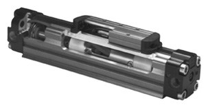 |
| The piston-lug rodless cylinder drives the load by a lug connected to the piston by a bolt that protrudes through a slot in the barrel. A seal running along the length of this slot prevents compressed air from leaking as the piston and lug traverse the stroke.
|
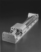 |
| Magnetic coupling of piston to lug allows rodless cylinder to drive and position loads using any dynamic seals. Model shown has integral bearings to carry load and ensure alignment.
|
 |
| Cutaway of cable cylinder shows how the piston is connected to the yoke through a cable assembly. This design uses a seal around the cable where it passes through each end cap.
|
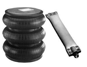 |
| Flexible-wall cylinders provide linear actuation without any dynamic seals. The type at left uses one or more flexible chambers (the one shown has three) that expand axially when pressurized. The hose type, right, expands radially when air is introduced. This type is best suited for short-stroke applications where actuation must occur over a relatively long length, especially when minimal clearance is available.
|
Spare the rod, double the stroke
The continuing trend to make machines smaller by taking advantage of more compact components is the driving force behind the increasingly widespread use of rodless cylinders. The three main types of rodless cylinders are the piston-lug version, the cable cylinder, and the flexible-wall cylinder. Most of these are designed for use with pneumatics, but some manufacturers provide ratings for low-pressure hydraulic service.
The piston-lug design works in a fashion similar to that of a conventional cylinder, but does not move the load through a rod. Instead, a bolt extends from the side of the piston out through a longitudinal slot in the barrel. A drive lug is attached to the end of the bolt and moves directly with the piston.
To seal the slot between the piston and lug, steel bands pressing against each other separate when the bolt passes by. Different piston widths are available to meet any bending moments imposed by a load. Stroke lengths of piston-lug cylinders can exceed 30 ft. Options include position switches, brakes, and carriages to support loads and maintain alignment.
A variation of the piston-lug cylinder uses a permanent magnet in the piston to create a magnetic field that links the piston to the lug through the cylinder barrel. This eliminates the need for a longitudinal slot in the barrel and, therefore, the need for any dynamic seals. Breakaway forces of the magnetic field can exceed 200 lb.
A new type of rodless cylinder uses a magnetic brake for precise motion and position control. This recently introduced cylinder is designed to achieve the precise control of proportional hydraulics using simple pneumatic directional control.
In a cable cylinder, as the piston moves inside the cylinder barrel, it pulls a cable attached to both sides of the piston. The cable wraps around a pulley mounted at each end and attaches to a yoke. As the double-acting piston moves in one direction, the yoke travels in the opposite direction because of the wrap around the pulleys.
Options include automatic cable tensioning, single-acting models, cable tracks for greater load stabilization and capacity, a pulley arrangement to double the stroke and speed, caliper disc brakes on the cable pulley, and reed switches. The cable also can be wound around a drum to provide rotational motion.
A variation of the cable cylinder relies on a metal band running over pulleys instead of a cable. Each end of the the upper yoke rides on the cylinder barrel for greater load stability and capacity, negating the need for a separate load carriage in many applications. These cylinders may be fitted with a brake that stops and holds the load anywhere along the stroke.
Flexible wall cylinders have evolved from designs that were originally made for vibration and isolation mounting. They consist of metal mounting plates fixed to a reinforced rubber chamber that extends and collapses, respectively, as it is pressurized and vented. They have generous lateral misalignment allowances and can actuate through an arc without a clevis mount.
Some precautions should be exercised when applying these cylinders. First, mechanical stops should be provided to limit the length of extension. Otherwise, an overrunning load could pull an end plate off the cylinder. Mechanical stops should also limit retraction, thereby preventing crushing the elastomeric portion of the cylinder between end plates. Alignment of these cylinders is much less critical than with conventional cylinders. However, relative torsional rotation between the end caps should be prevented to keep from having the elastomeric portion fail due to excessive shear stress.
An alternate design resembles a length of flexible hose sealed at both ends. With no pressure, the hose is flat; pumping air into it expands the hose into a tubular shape. Maximum stroke is approximately the ID of the inflated hose. Using a long length of such hose can generate very high force from a relatively low pressure. However, actuation force decreases with stroke length. This is because as the hose expands, it becomes more round, so a smaller area is in contact with the load to apply the force.
- Prev
- 1
- 2
- 3
- 4
Related Articles
- Fluid power digs into construction projects
- Low-speed/high-torque motors
- More reliable fluid power components?
- Fluid power safety in the workplace, part 6 2
- Fluid Power Negates the Sea’s Pitch-and-Roll
More Than Seals & Cylinders…………….Solutions!
More Than Seal & Cylinders………Solutions!