| SEAL INFORMATION | |
|---|---|
| MATERIAL | FABRIC REINFORCED
RUBBER URETHANE RING/NYLON ADAPTORS |
| TEMPERATURE RANGE | -35° to +220° F |
| PRESSURE RANGE | 0 to 10,000 PSI |
| SPEED | 1.5 FT/SEC |
| PART NUMBER | (Type of Seal) (ID) (CS) X (Height) |
-
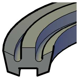
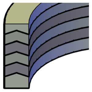 Our vee sets are the finest quality available in the industry. While all sets incorporate fabric reinforced rubber pressure rings, one or two urethane rings are included to improve low pressure sealing, when it is feasible. Most sets use nylon adaptors. Properly installed the pressure limits are as follows: 3,000 PSI = 4 VEES 5,000 PSI = 5 VEES 10,000 PSI = 6 VEES CONSTRUCTION CODE Example: FA-2U-3F-MA FA - 1 TOP ADAPTOR 2U - 2 URETHANE VEE RINGS 2F - 2 FABRIC VEE RINGS MA - 1 BOTTOM ADAPTOR V= FLUOROCARBON U= SPECIAL URETHANE VEE H= HYTREL W= WIPER INCLUDED
 -
 835 Homogeneous Rubber Vee Rings
SEAL INFORMATION MATERIAL 70 DURO BUNA-N TEMPERATURE RANGE -40° to +220° F PRESSURE RANGE 0 to 1,250 PSI SPEED 3 FT/SEC PART NUMBER (Prefix) - (Size) -
 PTFE Vee Rings
SEAL INFORMATION MATERIAL PTFE TEMPERATURE RANGE -100° to +400° F PRESSURE RANGE 0 to 5,000 PSI SPEED 12 FT/SEC PART NUMBER (Prefix) - (Size) -
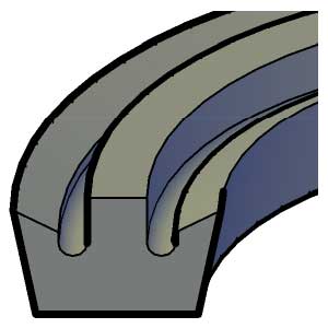
The individual vee rings and adaptors listed here are the same high quality product found in our assembled vee packing sets. Stocking individual vee rings allows you to assemble sets to your specific requirements.
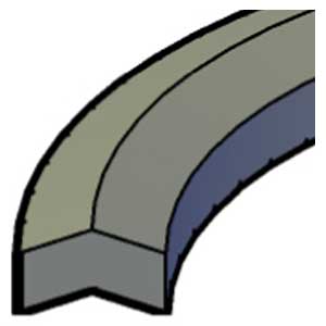
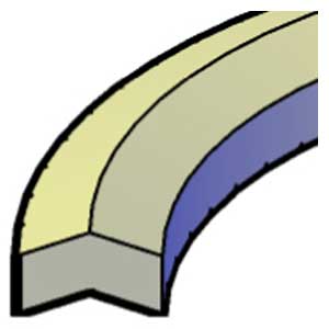
RING TYPES
T = TOP ADAPTOR - NYLON
B = BOTTOM ADAPTOR - NYLON/ NEO-FAB
F = NEO-FAB VEE RING
U = URETHANE VEE RING
R = RUBBER VEE RING.
(FOR MORE RUBBER VEE RINGS SEE OUR STYLE 835 RINGS)
SEAL INFORMATION MATERIAL NYLON, NEO-FAB URETHANE TEMPERATURE RANGE -35° to +220° F PRESSURE RANGE 0 to 5,000 PSI SPEED 1.5 FT/SEC PART NUMBER (Prefix) - (ID) (CS) (Type of Ring) -

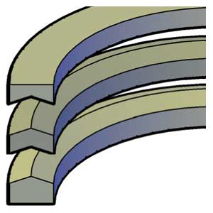
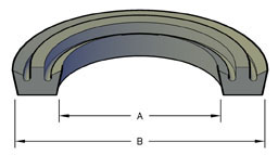
If your design is of medium to high pressure it is recommended that you utilize fabric reinforced rings. The following is a guide to pressure rating of multiple rings, including flat bottom rings.
SEAL INFORMATION MATERIAL FABRIC REINFORCED RUBBER
AND BUNA-NTEMPERATURE RANGE -40° TO +250° F PRESSURE RANGE SEE CHART BELOW SPEED 1.5 FT/SEC PART NUMBER (Prefix) - (ID) - (OD) A homogeneous ring may be also used for sealing at low pressure. Do not include the homogeneous ring in calculating pressure rating. Due to the different material, it is difficult to rate this type of ring. If you wish to use all homogeneous rings, tests should be conducted to verify design stability.
PRESSURE RATING OF MULTIPLE RINGS PRESSURE P.S.I. NUMBER OF RINGS 250 - 500 3 500 - 2,000 4 2,000 - 5,000 5 5,000 - 8,000 6 -
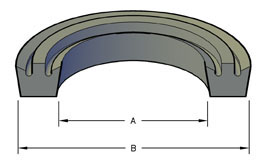 C = CARBOXILATED NITRILE
SEAL INFORMATION MATERIAL FABRIC REINFORCED RUBBER
AND BUNA-NTEMPERATURE RANGE -40° TO +250° F PRESSURE RANGE SEE CHART BELOW SPEED 1.5 FT/SEC PART NUMBER (Prefix) - (ID) - (OD) If your design is of medium to high pressure it is recommended that you utilize fabric reinforced rings. The following is a guide to pressure rating of multiple rings, including flat bottom rings.
PRESSURE RATING OF MULTIPLE RINGS PRESSURE P.S.I. NUMBER OF RINGS 250 - 500 3 500 - 2,000 4 2,000 - 5,000 5 5,000 - 8,000 6 A homogeneous ring may be also used for sealing at low pressure. Do not include the homogeneous ring in calculating pressure rating. Due to the different material, it is difficult to rate this type of ring. If you wish to use all homogeneous rings, tests should be conducted to verify design stability.
-

NOTE: The 6000 piston cups are center punched if there is no hole size indicated.
SEAL INFORMATION MATERIAL BUNA-N RUBBER TEMPERATURE RANGE -40° to +220° F PRESSURE RANGE 0 to 150 PSI SPEED 3 FT/SEC PART NUMBER (Piston Cup Type)(Bore) - (Hole Size) -
To obtain best results from any style of piston cup, it is recommended that the piston properly support the heel of the cup. Recommended diametral clearance between the piston and cylinder wall are as follows:
1" to 2-1/4" .005"
2-1/2" to 4-3/4" .008"
5" to 10" .010"
The height of the machined shoulder most frequently used to control squeeze on the heel of the cup is as follows:
Cups 1/8" thick .116/.119"
Cups 5/32" thick .146/.149"
Cups 3/16" thick .178/.181"
The follower plate should be approximately .110" smaller than the ID of the cup. To reduce any tendency of the cup to extrude under pressure a phonograph finish may be machined on the surface of the follower plate.
NOTE: The 8000 piston cups are center punched.
SEAL INFORMATION MATERIAL 90A URETHANE TEMPERATURE RANGE -65° to +220° F PRESSURE RANGE 0 to 1,200 PSI SPEED 3 FT/SEC PART NUMBER (Piston Cup Type)(Bore) - (Hole Size) -
Piston cups are constructed of rubberized fabric. Cups with no hole are center punched.
NOTE: If Product number ends in 'ED' the piston cups are specially sized for use in EDBRO Cylinders.SEAL INFORMATION MATERIAL COTTON FABRIC & RUBBER TEMPERATURE RANGE -35° to +220° F PRESSURE RANGE 0 to 2,500 PSI SPEED 1.5 FT/SEC PART NUMBER (Piston Cup Type)(Bore) - (Hole Size) -

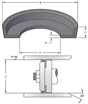
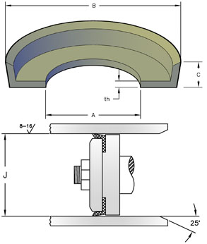
One Piece Double Acting Piston Cups
This complete piston cup with a simple, one-piece construction serves the same purpose as a multi-assembly unit and is more economical with easy maintenance, dependability and long life. The unique piston cup consists of homogeneous rubber bonded to a zinc coated steel plate. The center hole may be enlarged to accommodate larger piston rods. Recommended for pneumatic and low-pressure hydraulic applications.SEAL INFORMATION MATERIAL RUBBER LIP, ZINC COATED STEEL PLATE TEMPERATURE RANGE -40° to +220° F PRESSURE RANGE 0 to 800 PSI SPEED 3 FT/SEC PART NUMBER (Prefix) - (Bore Size) -

INSTALLATION OF PTFE PISTON SEALS
Installing PTFE piston seals is not always an easy task. The use of installation tools (Designated by a 'CTC-' product code prefix) is recommended but often not convenient when working with a wide variety of sizes and applications. Finger installations are practical with rings of smaller cross-sections. Using fingers or a rounded plastic stick, knead the ring over the piston into the groove. With rings of larger cross-sections it may be necessary to heat the ring. Warming the ring in water or oil at 130° F or 140° F for about 5 minutes will soften the material for easier installation. Always avoid inconsistent stretching or overstretching of the PTFE seal.To prevent the PTFE ring from snapping into the wrong groove, cover wear ring grooves with plastic tape.
After seal installation, assembly of the cylinder may be difficult if the piston seal is loose on the piston or the cylinder has an inadequate leading edge chamfer. In such cases, compress the piston seal with belting or a suitable hose clamp. If the piston seal must pass threads or any other sharp edges during the cylinder assembly, cover the edges with plastic tape or wrap. Note: Caterpillar part number are used as a refernce only. We do not imply that these part are original equipment parts.
SEAL INFORMATION MATERIAL BUNA-N RUBBER SEAL
- HARD PLASTIC BACK-UPSTEMPERATURE RANGE -40° to +220° F PRESSURE RANGE 0 to 6,000 PSI -

A heavy duty double-acting assembly, the capped piston T-seal exhibits excellent sealability, extrusion resistance and wearability. T-seals with 'BR' suffix utilize a Bronze Filled PTFE cap instead of the standard Glass Filled PTFE cap.
INSTALLATION OF PTFE PISTON SEALS
Installing PTFE piston seals is not always an easy task. The use of installation tools (Designated by a 'CTC-' product code prefix) is recommended but often not convenient when working with a wide variety of sizes and applications. Finger installations are practical with rings of smaller cross-sections. Using fingers or a rounded plastic stick, knead the ring over the piston into the groove. With rings of larger cross-sections it may be necessary to heat the ring. Warming the ring in water or oil at 130° F or 140° F for about 5 minutes will soften the material for easier installation. Always avoid inconsistent stretching or overstretching of the PTFE seal.To prevent the PTFE ring from snapping into the wrong groove, cover wear ring grooves with plastic tape.
After seal installation, assembly of the cylinder may be difficult if the piston seal is loose on the piston or the cylinder has an inadequate leading edge chamfer. In such cases, compress the piston seal with belting or a suitable hose clamp. If the piston seal must pass threads or any other sharp edges during the cylinder assembly, cover the edges with plastic tape or wrap.
SEAL INFORMATION MATERIAL PTFE CAP
NYLON BACK-UP
RUBBER ENERGIZERTEMPERATURE RANGE -40° to +220° F PRESSURE RANGE 0 to 6,000 PSI SPEED 4.5 FT/SPEED> PART NUMBER (Prefix) - (Bore Size) -

T-Seals are non-spiraling and extrusion resistant to 5,000 psi with improved tolerances.
IB = Intermediate Base, WB = Wide Base
Intermediate and Wide Base T-Seals are designed to fit MIL-5514F o-ring glands only and interchange with 1 o-ring / 1 back-up ring and 1 o-ring / 2 back-up ring grooves, respectively.SEAL INFORMATION MATERIAL BUNA-N RUBBER SEAL - HARD PLASTIC BACK-UPS TEMPERATURE RANGE -35° to +220° F PRESSURE RANGE 0 to 5,000 PSI SPEED 3 FT/SEC PART NUMBER (Prefix) - (Size)